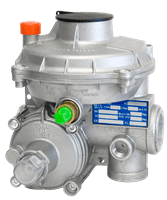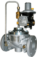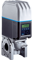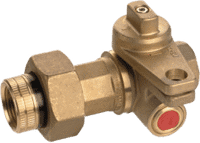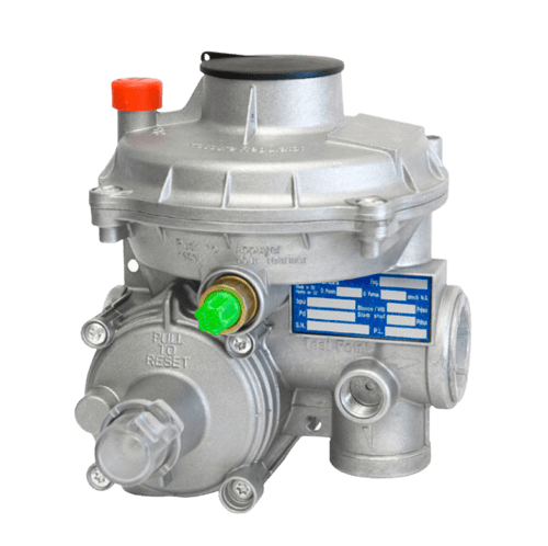
FE Gas Pressure Regulator
The Mod. FE is a two-stage direct-operated gas pressure regulator by Pietro Fiorentini, and is equipped with integrated slam shut for maximum downstream pressure. Ideal for low pressure natural gas distribution networks for residential users.
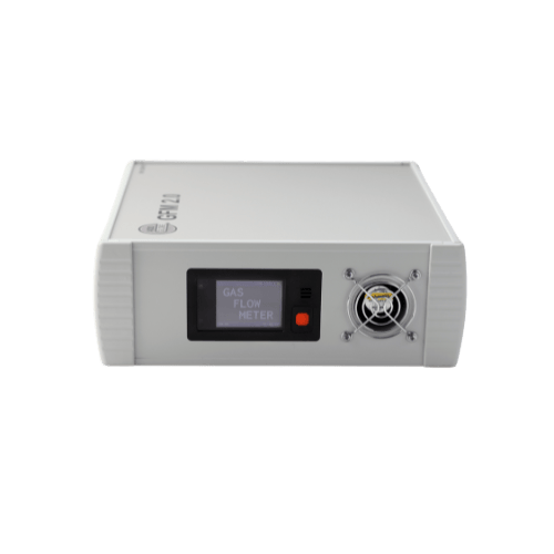
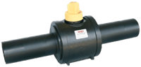
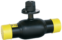
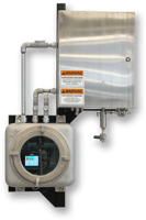
Gas Flow Meter 2.0

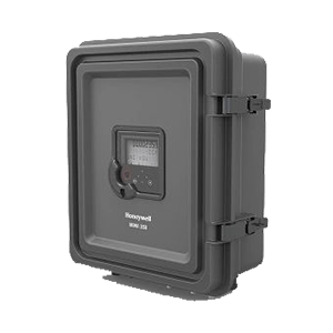
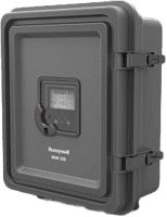
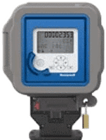
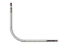
MiWireless 350 Pressure Recorder
The MiWireless350 platform leverages the latest innovations in battery operated instruments such as the EC 350 and ERX 350, and low power 4G cellular radios such as Cloud Link R100 or Cloud Link with Cat M1 radio support.
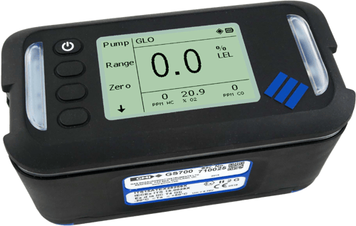
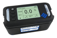
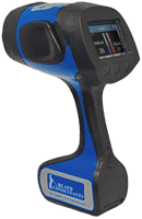
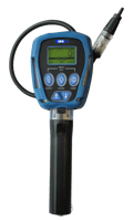
GS700 Series Portable Infrared Gas Leak Detector
The GS700 utilizes the latest infrared gas detection technology in a robust and reliable design. It provides intelligent data-logging functionality combined with optional GPS mapping to simplify data gathering and easily syncs with our cloud based Instrument Management System (IMS) to support reporting and compliance.
Featured Products View All Products